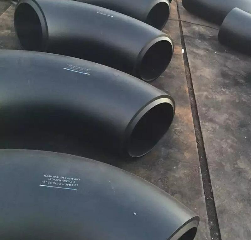
1. Buig buizen:
Buisbuigen is de overkoepelende term voor metaalvormprocessen die worden gebruikt om buizen of buizen permanent te vormen. Er moet onderscheid worden gemaakt tussen vormgebonden en vrije vormbuigprocedures, evenals tussen warmteondersteunde en koude vervormingsprocedures.
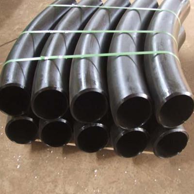
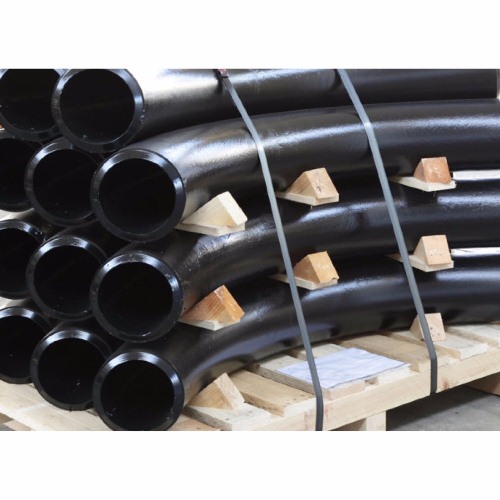
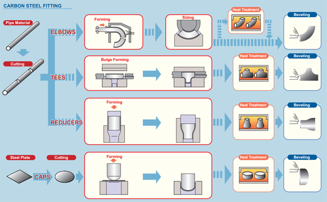
2. Processen:
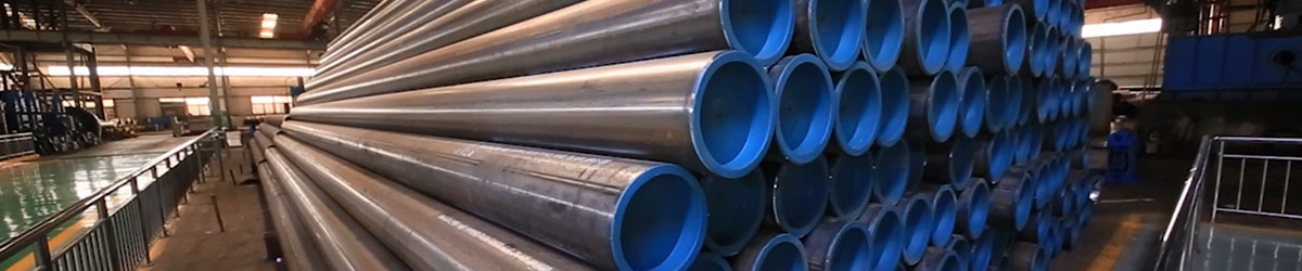
Het buigen van buizen begint als proces met het laden van een buis in een buizen- of pijpenbuiger en het op zijn plaats vastklemmen tussen twee matrijzen, het klemblok en de vormmatrijs. De buis wordt ook losjes vastgehouden door twee andere matrijzen, de wissermatrijs en de drukmatrijs.
Bij het buigen van buizen wordt gebruik gemaakt van mechanische kracht om pijpen of buizen uit voorraadmateriaal tegen een matrijs te duwen, waardoor de pijp of buis wordt gedwongen zich aan te passen aan de vorm van de matrijs. Vaak wordt de standaardbuis stevig op zijn plaats gehouden terwijl het uiteinde wordt gedraaid en rond de matrijs wordt gerold. Andere vormen van verwerking, waaronder het door rollen duwen van het materiaal, waardoor het in een eenvoudige bocht wordt gebogen. Bij sommige buisbuigbewerkingen wordt een doorn in de buis geplaatst om instorten te voorkomen. De buis wordt op spanning gehouden door een veegmatrijs om plooien tijdens spanning te voorkomen. Een wissermatrijs is meestal gemaakt van een zachtere legering zoals aluminium of messing om krassen of beschadiging van het gebogen materiaal te voorkomen.
Persbuigen:
Persbuigen is waarschijnlijk het eerste buigproces dat wordt toegepast op koude buizen en buizen. Bij dit proces wordt een matrijs in de vorm van de bocht tegen de buis gedrukt, waardoor de buis wordt gedwongen om in de vorm van de bocht te passen. Omdat de buis niet inwendig wordt ondersteund, vindt er enige vervorming van de vorm van de buis plaats, waardoor een ovale doorsnede ontstaat. Dit proces wordt gebruikt wanneer een consistente dwarsdoorsnede van de buis niet vereist is. Hoewel een enkele matrijs verschillende vormen kan produceren, werkt deze alleen voor buis en straal van één maat.
Roterend trekbuigen:
Volledige tooling voor roterend trekbuigen
Roterend trekbuigen (RDB) is een precieze technologie, omdat er wordt gebogen met behulp van gereedschappen of "matrijzensets" die een constante hartlijnradius (CLR) hebben, ook wel aangegeven als gemiddelde buigradius (Rm).
Rollenbuigen:
Tijdens het rolbuigproces wordt de buis, de extrusie of de vaste stof door een reeks rollen (meestal drie) geleid die druk uitoefenen op de buis, waardoor de buigradius in de buis geleidelijk verandert. De rolbuigers in piramidestijl hebben één bewegende rol, meestal de bovenste rol. Rolbuigers van het dubbele knijptype hebben twee verstelbare rollen, meestal de onderste rollen, en een vaste bovenste rol. Deze buigmethode veroorzaakt zeer weinig vervorming in de dwarsdoorsnede van de buis. Dit proces is geschikt voor het produceren van pijprollen en voor lange, zachte bochten zoals die worden gebruikt in truss-systemen.
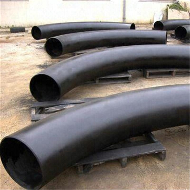
Inductie buigen:
Rond een klein gedeelte van de buis op het buigpunt wordt een inductiespoel geplaatst. Vervolgens wordt het inductieverwarmd tot tussen 800 en 2200 graden Fahrenheit (430 en 1200 C). Terwijl de buis heet is, wordt er druk op de buis uitgeoefend om deze te buigen. De buis kan vervolgens worden geblust met lucht- of waternevel of worden gekoeld tegen omgevingslucht.
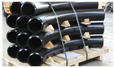
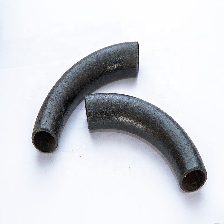
Inductiebuigen wordt gebruikt voor het maken van bochten voor een breed scala aan toepassingen, zoals (dunwandige) pijpleidingen voor zowel de stroomopwaartse als stroomafwaartse en on- en offshore segmenten van de petrochemische industrie, constructiedelen met grote radius voor de bouwsector, dikwandige bochten met korte radius voor de energieopwekkingsindustrie en stadsverwarmingssystemen.
Grote voordelen van inductiebuigen zijn:
geen doorns nodig
buigradii en hoeken (1°-180°) vrij te kiezen
zeer nauwkeurige buigradii en hoeken
nauwkeurige pijpspoelen kunnen eenvoudig worden geproduceerd
er kunnen aanzienlijke besparingen worden behaald op veldlassen
Er kan een breed scala aan buismaten in één machine worden ondergebracht (1” OD tot en met 80” OD)
uitstekende wandverdunning en ovaliteitswaarden
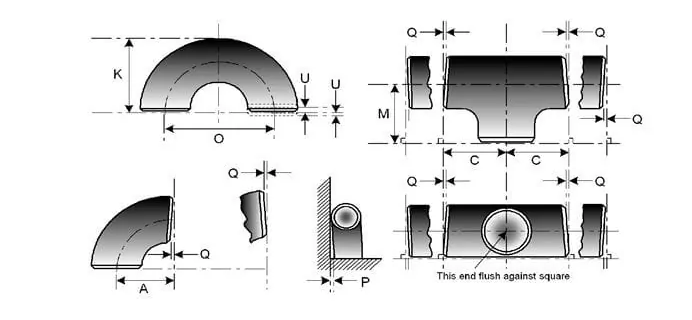
Voor smeedproduct (WP) wordt de afmeting vermeld in
ASME B16.9 - standaard voor in de fabriek gemaakte gesmeed stomplasfittingen voor maat NPS 1⁄₂ tot NPS 48” en
En B16.28 - standaard voor smeedstalen stompgelaste ellebogen en retourstukken met korte radius voor maat NPS 1⁄₂ tot NPS 24”
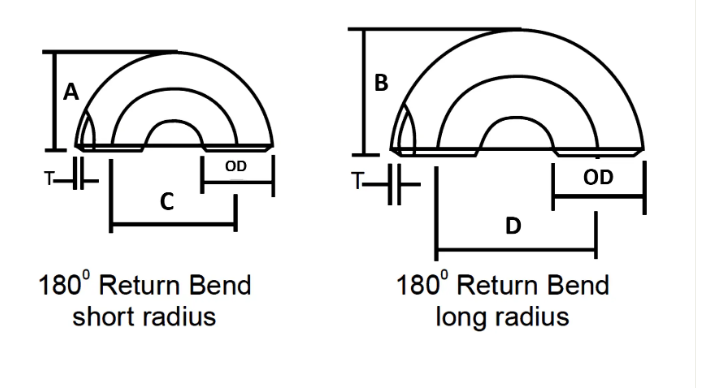
| NOMINALE LEIDINGMAAT | BUITENDIAMETER | TERUG NAAR GEZICHT | CENTRUM NAAR CENTRUM | ||
| Duim. | OD | A | B | C | D |
| 1/2 | 21.3 | 48 | – | 76 | – |
| 3/4 | 26.7 | 43 | – | 57 | – |
| 1 | 33.4 | 56 | 41 | 76 | 51 |
| 1 1/4 | 42.2 | 70 | 52 | 95 | 64 |
| 1 1/2 | 48,3 | 83 | 62 | 114 | 76 |
| 2 | 60,3 | 106 | 81 | 152 | 102 |
| 2 1/2 | 73 | 132 | 100 | 191 | 127 |
| 3 | 88,9 | 159 | 121 | 229 | 152 |
| 3 1/2 | 101,6 | 184 | 140 | 267 | 178 |
| 4 | 114,3 | 210 | 159 | 305 | 203 |
| 5 | 141,3 | 262 | 197 | 381 | 254 |
| 6 | 168,3 | 313 | 237 | 457 | 305 |
| 8 | 219.1 | 414 | 313 | 610 | 406 |
| 10 | 273,1 | 518 | 391 | 762 | 508 |
| 12 | 323,9 | 619 | 467 | 914 | 610 |
| 14 | 355,6 | 711 | 533 | 1067 | 711 |
| 16 | 406,4 | 813 | 610 | 1219 | 813 |
| 18 | 457,2 | 914 | 686 | 1372 | 914 |
| 20 | 508 | 1016 | 762 | 1524 | 1016 |
| 22 | 559 | 1118 | 838 | 1676 | 1118 |
| 24 | 610 | 1219 | 914 | 1829 | 1219 |
Afmetingen buisfittingen Tolerantie volgens ASME B16.9
| NOMINALE LEIDINGMAAT | ALLE FITTING | ALLE FITTING | ALLE FITTING | ELLEBOGEN EN T-stukken | 180 GRADEN RETOURBOCHTEN | 180 GRADEN RETOURBOCHTEN | 180 GRADEN RETOURBOCHTEN | VERTRAGERS | CAPS |
| NPS | Buitendiameter bij schuine kant (1), (2) | Identiteitskaart aan het einde (1), (3), (4) | Wanddikte (3) | Afmeting hart tot einde A,B,C,M | Centrum-op-centrum O | Met de rug tegen elkaar K | Uitlijning van de uiteinden U | Totale lengte H | Totale lengte E |
| ½ tot 2½ | 0,06 -0,03 | 0,03 | Niet minder dan 87,5% van de nominale dikte | 0,06 | 0,25 | 0,25 | 0,03 | 0,06 | 0,12 |
| 3 tot 3 ½ | 0,06 | 0,06 | Niet minder dan 87,5% van de nominale dikte | 0,06 | 0,25 | 0,25 | 0,03 | 0,06 | 0,12 |
| 4 | 0,06 | 0,06 | Niet minder dan 87,5% van de nominale dikte | 0,06 | 0,25 | 0,25 | 0,03 | 0,06 | 0,12 |
| 5 tot 8 | 0,09 -0,06 | 0,06 | Niet minder dan 87,5% van de nominale dikte | 0,06 | 0,25 | 0,25 | 0,03 | 0,06 | 0,25 |
| 10 tot 18 | 0,16 -0,12 | 0,12 | Niet minder dan 87,5% van de nominale dikte | 0,09 | 0,38 | 0,25 | 0,06 | 0,09 | 0,25 |
| 20 tot 24 | 0,25 -0,19 | 0,19 | Niet minder dan 87,5% van de nominale dikte | 0,09 | 0,38 | 0,25 | 0,06 | 0,09 | 0,25 |
| 26 tot 30 | 0,25 -0,19 | 0,19 | Niet minder dan 87,5% van de nominale dikte | 0,12 | … | … | … | 0,19 | 0,38 |
| 32 tot 48 | 0,25 -0,19 | 0,19 | Niet minder dan 87,5% van de nominale dikte | 0,19 | … | … | … | 0,19 | 0,38 |
Nikkellegering
ASTM / ASME SB 336 UNS 2200 (NIKKEL 200), UNS 2201 (NIKKEL 201), UNS 4400 (MONEL 400), UNS 8020 (LEGERING 20/20 CB 3, UNS 8825 INCONEL (825), UNS 6600 (INCONEL 600), UNS 6601 (INCONEL 601), UNS 6625 (INCONEL 625), UNS 10276 (HASTELLOY C 276)
Roestvrij staal
ASTM / ASME SA 403 GR WP “S” / “W” / “WX” 304, 304L, 304H, 304N, 304LN, 309, 310H, 316, 316H, 317, 317L, 321, 321H, 347, 347 H.
Dubbelzijdig staal
ASTM / ASME SA 815 UNS NR.S 31803, S 32205, S 32550, S 32750, S 32760.
Koolstofstaal
ASTM / ASME A 234 WPB, WPC ASTM / ASME A 860 WPHY 42, WPHY 46, WPHY 52, WPH 60, WPHY 65 & WPHY 70.
Gelegeerd staal
ASTM / ASME A 234 WP 1, WP 5, WP 9, WP 11, WP 12, WP 22, WP 23, WP 91.
| Chemische samenstelling Inhoud | Mechanische eigenschappen | ||||||||||
| Materiaal nr | C | Mn | Si | S | P | Cr | Mo | Ni | Treksterkte | Opbrengststerkte | Verlenging |
| A234 WPB | ≤0,3 | 0,29-1,06 | ≥0,1 | ≤0,058 | ≤0,05 | / | / | / | 415-585 | ≥240 | ≥30 |
| A234 WP5 | ≤0,15 | ≤0,6 | ≤0,5 | ≤0,04 | ≤0,03 | 4-6 | 0,44-0,65 | / | 415-585 | ≥205 | ≥20 |
| A403 WP304 | ≤0,08 | ≤2 | ≤1 | ≤0,040 | ≤0,030 | 18-20 | / | 8-11 | ≥515 | ≥205 | ≥30 |
| A403WP316L | ≤0,03 | ≤2 | ≤1 | ≤0,045 | ≤0,03 | 16-18 | 2-3 | 10-15 | ≥485 | ≥170 | ≥30 |
| WPHY60 | ≤0,20 | 1-1.45 | 0,15-0,4 | ≤0,015 | ≤0,030 | / | / | / | ≥515 | ≥415 | / |
Licht geolied, zwart gelakt, PE /3PE anticorrosiecoating
Vereisten voor hete inductiebochtplanken
We concentreren ons op elke procedure om de kwaliteit te garanderen, het pakket dat we gewoonlijk nemen is het planken van de stalen buisellebogen met milieuvriendelijke polyzakken, en vervolgens in gratis begassing houten kisten of houten platen. We accepteren ook een aangepast pakket zoals OEM door middel van onderhandelingen.
- Het materiaal moet gereed voor export worden verpakt op een manier die gemakkelijke hantering mogelijk maakt en schade voorkomt. De verkoper zal zijn standaardverpakkingsprocedure ter goedkeuring aan de koper voorleggen.
- Open uiteinden van fittingen en flenzen moeten worden geleverd met stevige plastic beschermpluggen of -kappen. Voor afgeschuinde uiteinden moeten de doppen het volledige gebied van de afschuining beschermen.
- Er moet waterdicht barrièremateriaal worden gebruikt voor roestvrijstalen materiaal om te beschermen tegen chlooraantasting door blootstelling aan de zoute wateratmosfeer.
- Artikelen van koolstofstaal en roestvrij staal mogen niet samen worden opgeslagen en moeten afzonderlijk worden verpakt.