1. チューブを曲げる:
チューブ曲げは、パイプやチューブを永久的に形成するために使用される金属成形プロセスの総称です。成形曲げ手順と自由成形手順、および熱支持成形手順と冷間成形手順を区別する必要があります。
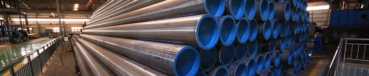
2. プロセス:
プロセスとしてのチューブ曲げは、チューブをチューブまたはパイプ ベンダーにロードし、クランプ ブロックと成形ダイの 2 つのダイの間の所定の位置にクランプすることから始まります。チューブは、他の 2 つのダイ、ワイパー ダイと加圧ダイによっても緩く保持されます。
チューブを曲げるプロセスでは、機械力を使用して素材のパイプまたはチューブを金型に押しつけ、パイプまたはチューブを金型の形状に強制的に適合させます。多くの場合、ストックチューブは、端が回転してダイの周りを転がる間、所定の位置にしっかりと保持されます。他の形式の加工には、素材をローラーに押し込んで単純な曲線に曲げる方法が含まれます。[2]一部のチューブ曲げ加工では、つぶれを防ぐためにチューブの内側にマンドレルを入れます。チューブはワイパーダイによって張力がかかった状態に保持され、応力時のしわを防ぎます。ワイパーダイは通常、曲げられる材料に傷や損傷を与えないように、アルミニウムや真鍮などの柔らかい合金で作られています。
プレス曲げ:
プレス曲げは、おそらくコールドパイプやチューブに使用される最初の曲げプロセスです。このプロセスでは、曲げの形状をしたダイがパイプに押し付けられ、パイプが曲げの形状にフィットするように強制されます。パイプは内部で支持されていないため、パイプの形状が多少変形し、断面が楕円形になります。このプロセスは、パイプの一貫した断面が必要ない場合に使用されます。 1 つの金型でさまざまな形状を作成できますが、1 つのサイズのチューブと半径に対してのみ機能します。
回転絞り曲げ:
回転絞り曲げ用のフルツール
回転絞り曲げ (RDB) は、一定の中心線半径 (CLR)、または平均曲げ半径 (Rm) で示されるツーリングまたは「ダイ セット」を使用して曲げるため、精密な技術です。
ロール曲げ:
ロール曲げプロセスでは、パイプ、押出成形品、または固体が一連のローラー (通常は 3 つ) を通過し、パイプに圧力が加えられ、パイプの曲げ半径が徐々に変化します。ピラミッド型のロール ベンダーには 1 つの可動ロール (通常は上部ロール) があります。ダブルピンチタイプのロールベンダーには、通常は下部ロールと固定上部ロールの 2 つの調整可能なロールがあります。この曲げ方法ではパイプ断面の変形がほとんどありません。このプロセスは、パイプのコイルや、トラス システムで使用されるような長く緩やかな曲げの製造に適しています。
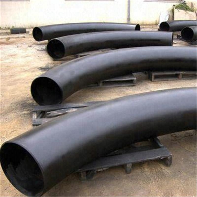
高周波曲げ:
誘導コイルは、パイプの屈曲点の小さな部分の周囲に配置されます。その後、華氏 800 ~ 2,200 度 (430 ~ 1,200 ℃) まで誘導加熱されます。パイプが熱いうちに圧力を加えてパイプを曲げます。その後、パイプを空気または水スプレーで急冷するか、周囲空気に対して冷却します。
高周波曲げは、石油化学産業の上流と下流、陸上と沖合のセグメント向けの(薄肉)パイプライン、建設産業向けの大きな半径の構造部品など、幅広い用途の曲げを製造するために使用されます。発電産業や都市暖房システム向けの厚肉で半径の短い屈曲部。
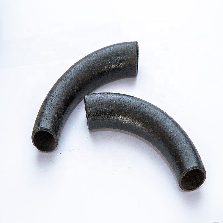
高周波曲げの大きな利点は次のとおりです。
マンドレルは必要ありません
曲げ半径と角度(1°~180°)を自由に選択可能
高精度の曲げ半径と角度
正確なパイプスプールを簡単に製造できます
現場溶接で大幅な節約が可能
1 台の機械で幅広いパイプ サイズに対応可能 (外径 1 インチから外径 80 インチ)
優れた薄肉化と楕円率の値
鍛造製品 (WP) の場合、寸法は以下でカバーされます。
ASME B16.9 - サイズ NPS 1⁄2 ~ NPS 48 インチの工場製鍛突合せ溶接継手の標準です。
また、B16.28-は、鍛鋼突合せ溶接ショートラジアスエルボの標準であり、サイズNPS 1⁄₂からNPS 24インチのリターンとなります。
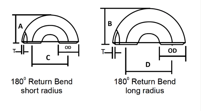
| 公称パイプサイズ | 外径 | 顔に戻る | 中心から中心まで | ||
| インチ。 | OD | A | B | C | D |
| 1/2 | 21.3 | 48 | – | 76 | – |
| 3/4 | 26.7 | 43 | – | 57 | – |
| 1 | 33.4 | 56 | 41 | 76 | 51 |
| 1 1/4 | 42.2 | 70 | 52 | 95 | 64 |
| 1 1/2 | 48.3 | 83 | 62 | 114 | 76 |
| 2 | 60.3 | 106 | 81 | 152 | 102 |
| 2 1/2 | 73 | 132 | 100 | 191 | 127 |
| 3 | 88.9 | 159 | 121 | 229 | 152 |
| 3 1/2 | 101.6 | 184 | 140 | 267 | 178 |
| 4 | 114.3 | 210 | 159 | 305 | 203 |
| 5 | 141.3 | 262 | 197 | 381 | 254 |
| 6 | 168.3 | 313 | 237 | 457 | 305 |
| 8 | 219.1 | 414 | 313 | 610 | 406 |
| 10 | 273.1 | 518 | 391 | 762 | 508 |
| 12 | 323.9 | 619 | 467 | 914 | 610 |
| 14 | 355.6 | 711 | 533 | 1067 | 711 |
| 16 | 406.4 | 813 | 610 | 1219 | 813 |
| 18 | 457.2 | 914 | 686 | 1372 | 914 |
| 20 | 508 | 1016 | 762 | 1524年 | 1016 |
| 22 | 559 | 1118 | 838 | 1676年 | 1118 |
| 24 | 610 | 1219 | 914 | 1829年 | 1219 |
パイプ継手の寸法公差は ASME B16.9 に準拠
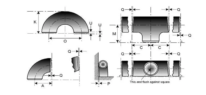
| 公称パイプサイズ | すべての付属品 | すべての付属品 | すべての付属品 | 肘とティー | 180 度のリターンベンド | 180 度のリターンベンド | 180 度のリターンベンド | 減速機 | 大文字 |
| NPS | ベベル部の外径 (1)、(2) | 末尾のID (1)、(3)、(4) | 肉厚 (3) | 中心から端までの寸法 A、B、C、M | 中心間 O | 背中合わせのK | 端の位置合わせ U | 全長H | 全長E |
| 1/2 ~ 2 1/2 | 0.06 -0.03 | 0.03 | 公称厚さの87.5%以上 | 0.06 | 0.25 | 0.25 | 0.03 | 0.06 | 0.12 |
| 3から3 1/2 | 0.06 | 0.06 | 公称厚さの87.5%以上 | 0.06 | 0.25 | 0.25 | 0.03 | 0.06 | 0.12 |
| 4 | 0.06 | 0.06 | 公称厚さの87.5%以上 | 0.06 | 0.25 | 0.25 | 0.03 | 0.06 | 0.12 |
| 5~8 | 0.09 -0.06 | 0.06 | 公称厚さの87.5%以上 | 0.06 | 0.25 | 0.25 | 0.03 | 0.06 | 0.25 |
| 10~18 | 0.16 -0.12 | 0.12 | 公称厚さの87.5%以上 | 0.09 | 0.38 | 0.25 | 0.06 | 0.09 | 0.25 |
| 20~24 | 0.25 -0.19 | 0.19 | 公称厚さの87.5%以上 | 0.09 | 0.38 | 0.25 | 0.06 | 0.09 | 0.25 |
| 26~30 | 0.25 -0.19 | 0.19 | 公称厚さの87.5%以上 | 0.12 | … | … | … | 0.19 | 0.38 |
| 32~48 | 0.25 -0.19 | 0.19 | 公称厚さの87.5%以上 | 0.19 | … | … | … | 0.19 | 0.38 |
ニッケル合金
ASTM / ASME SB 336 UNS 2200(ニッケル200)、UNS 2201(ニッケル201)、UNS 4400(Monel 400)、UNS 8020(Alloy 20 /20 CB 3、UNS 8825 Incenel(825)、UNS 6600(Inconel 600)、 UNS 6601 (インコネル 601)、UNS 6625 (インコネル 625)、UNS 10276 (ハステロイ C 276)
ステンレス鋼
ASTM / ASME SA 403 GR WP “S” / “W” / “WX” 304 、 304L、 304H、 304N、 304LN、 309、 310H、 316、 316H、 317、 317L、 321、 321H、 347、 347 H。
二相鋼
ASTM / ASME SA 815 UNS NO.S 31803、S 32205、S 32550、S 32750、S 32760。
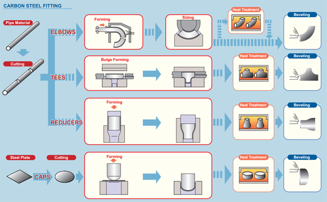
炭素鋼
ASTM / ASME A 234 WPB、WPC ASTM / ASME A 860 WPHY 42、WPHY 46、WPHY 52、WPH 60、WPHY 65 および WPHY 70。
合金鋼
ASTM / ASME A 234 WP 1、WP 5、WP 9、WP 11、WP 12、WP 22、WP 23、WP 91。
| 化学成分含有量 | 機械的性質 | ||||||||||
| 材質NO | C | Mn | Si | S | P | Cr | Mo | Ni | 抗張力 | 降伏強さ | 伸長 |
| A234 WPB | ≤0.3 | 0.29~1.06 | ≥0.1 | ≤0.058 | ≤0.05 | / | / | / | 415-585 | ≥240 | 30以上 |
| A234 WP5 | ≤0.15 | ≤0.6 | ≤0.5 | ≤0.04 | ≤0.03 | 4-6 | 0.44~0.65 | / | 415-585 | ≥205 | 20以上 |
| A403 WP304 | ≤0.08 | ≤2 | ≤1 | ≤0.040 | ≤0.030 | 18-20 | / | 8-11 | ≥515 | ≥205 | 30以上 |
| A403 WP316L | ≤0.03 | ≤2 | ≤1 | ≤0.045 | ≤0.03 | 16-18 | 2-3 | 10-15 | ≥485 | ≥170 | 30以上 |
| WPHY60 | ≤0.20 | 1-1.45 | 0.15~0.4 | ≤0.015 | ≤0.030 | / | / | / | ≥515 | ≥415 | / |
軽油、黒色塗装、PE/3PE防食コーティング
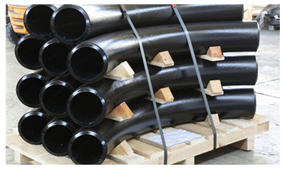
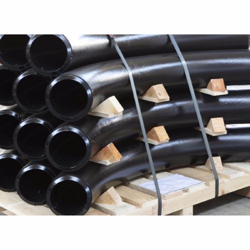
熱間誘導曲げ板張りの要件
私たちは品質を保証するためにあらゆる手順に焦点を当てています。通常、パッケージは鋼管エルボを環境ポリ袋で板張りし、無料の燻蒸木製ケースまたは木製プレートに入れます。交渉によりOEMなどのカスタマイズされたパッケージも受け入れます。
- 材料は、取り扱いが容易で損傷を防ぐ方法で輸出に備えて梱包されなければなりません。ベンダーは標準的な梱包手順を購入者に提出して承認を得る必要があります。
- フィッティングとフランジの開放端には、頑丈なプラスチック製の保護プラグまたはキャップが付属します。面取りされた端の場合、キャップは面取りの全領域を保護する必要があります。
- 塩水雰囲気への曝露による塩素の攻撃から保護するために、ステンレス鋼材料には防水バリア材料を使用する必要があります。
- 炭素鋼とステンレス鋼のアイテムは一緒に保管することができず、別々に梱包する必要があります。