1. Piegare il tubo:
La piegatura dei tubi è il termine generico per i processi di formatura dei metalli utilizzati per formare in modo permanente tubi o tubature. È necessario distinguere tra procedure di piegatura a forma vincolata e a forma libera, nonché tra procedure di formatura supportata dal calore e a freddo.
2. Processi:
Il processo di piegatura dei tubi inizia con il caricamento di un tubo in una curvatubi o una curvatubi e il bloccaggio in posizione tra due matrici, il blocco di bloccaggio e la matrice di formatura. Il tubo è inoltre trattenuto liberamente da altri due stampi, lo stampo raschiatore e lo stampo di pressione.
Il processo di piegatura del tubo prevede l'uso della forza meccanica per spingere il tubo o il tubo del materiale grezzo contro uno stampo, costringendo il tubo o il tubo a conformarsi alla forma dello stampo. Spesso, il tubo grezzo viene tenuto saldamente in posizione mentre l'estremità viene ruotata e arrotolata attorno allo stampo. Altre forme di lavorazione includono la spinta del materiale attraverso rulli che lo piegano in una curva semplice.[2] Per alcune lavorazioni di piegatura dei tubi, un mandrino viene posizionato all'interno del tubo per impedirne il collasso. Il tubo è tenuto in tensione da una matrice raschiante per evitare qualsiasi piega durante lo sforzo. Una matrice raschiante è solitamente realizzata in una lega più morbida come alluminio o ottone per evitare di graffiare o danneggiare il materiale da piegare.
Pressopiegatura:
La piegatura a pressione è probabilmente il primo processo di piegatura utilizzato su tubi e tubazioni a freddo. In questo processo uno stampo a forma di curva viene premuto contro il tubo costringendo il tubo ad adattarsi alla forma della curva. Poiché il tubo non è supportato internamente, si verifica una certa deformazione della forma del tubo, che risulta in una sezione trasversale ovale. Questo processo viene utilizzato laddove non è richiesta una sezione trasversale coerente del tubo. Sebbene un singolo stampo possa produrre varie forme, funziona solo per tubi e raggi della stessa dimensione.
Piegatura a disegno rotatorio:
Attrezzatura completa per la piegatura a rotazione
La piegatura rotativa (RDB) è una tecnologia precisa, poiché esegue la piegatura utilizzando attrezzature o "staffe" che hanno un raggio centrale costante (CLR), alternativamente indicato come raggio medio di curvatura (Rm).
Piegatura del rullo:
Durante il processo di curvatura a rulli, il tubo, l'estrusione o il solido vengono fatti passare attraverso una serie di rulli (tipicamente tre) che esercitano pressione sul tubo modificando gradualmente il raggio di curvatura del tubo. Le piegatrici a rulli in stile piramidale hanno un rullo mobile, solitamente il rullo superiore. Le piegatrici a rulli a doppia presa hanno due rulli regolabili, solitamente i rulli inferiori, e un rullo superiore fisso. Questo metodo di piegatura provoca una deformazione minima nella sezione trasversale del tubo. Questo processo è adatto alla produzione di bobine di tubi e di curve lunghe e dolci come quelle utilizzate nei sistemi a traliccio.
Piegatura ad induzione:
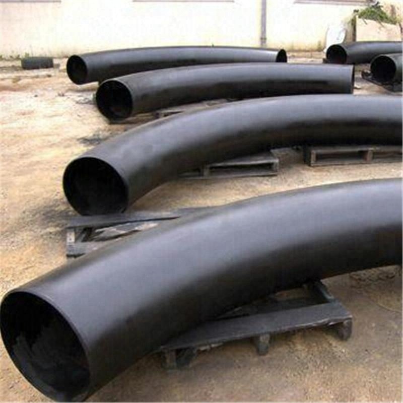
Una bobina di induzione è posizionata attorno a una piccola sezione del tubo nel punto di curvatura. Viene quindi riscaldato per induzione tra 800 e 2.200 gradi Fahrenheit (430 e 1.200 C). Mentre il tubo è caldo, viene esercitata una pressione sul tubo per piegarlo. Il tubo può quindi essere raffreddato con aria o acqua nebulizzata oppure essere raffreddato contro l'aria ambiente.
La piegatura a induzione viene utilizzata per produrre curve per un'ampia gamma di applicazioni, come linee di tubazioni (a pareti sottili) sia per i segmenti upstream che downstream e on-shore e off-shore dell'industria petrolchimica, parti strutturali ad ampio raggio per l'industria delle costruzioni, Curve a corto raggio e con pareti spesse per l'industria della produzione di energia e sistemi di riscaldamento urbano.
I grandi vantaggi della piegatura ad induzione sono:
non c'è bisogno di mandrini
i raggi e gli angoli di curvatura (1°-180°) possono essere selezionati liberamente
raggi e angoli di curvatura estremamente accurati
è possibile produrre facilmente bobine di tubi precise
si possono ottenere notevoli risparmi sulle saldature in campo
un'ampia gamma di dimensioni di tubi può essere alloggiata in un'unica macchina (da 1" OD a 80" OD)
ottimi valori di assottigliamento delle pareti e di ovalizzazione
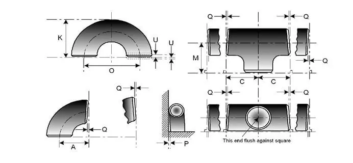
Per il prodotto lavorato (WP), la dimensione è inclusa
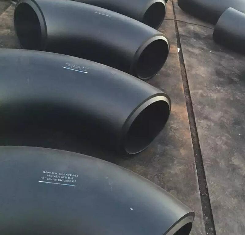
ASME B16.9- che è lo standard per i raccordi a saldare di testa realizzati in fabbrica per dimensioni da NPS 1⁄₂ a NPS 48" e
E B16.28, che è lo standard per gomiti e ritorni a raggio corto con saldatura di testa in acciaio battuto per dimensioni da NPS 1⁄₂ a NPS 24"
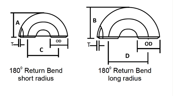
| DIMENSIONE NOMINALE DEL TUBO | DIAMETRO ESTERNO | TORNA ALLA FACCIA | DA CENTRO A CENTRO | ||
| Pollice. | OD | A | B | C | D |
| 1/2 | 21.3 | 48 | – | 76 | – |
| 3/4 | 26.7 | 43 | – | 57 | – |
| 1 | 33.4 | 56 | 41 | 76 | 51 |
| 1 1/4 | 42.2 | 70 | 52 | 95 | 64 |
| 1 1/2 | 48.3 | 83 | 62 | 114 | 76 |
| 2 | 60.3 | 106 | 81 | 152 | 102 |
| 2 1/2 | 73 | 132 | 100 | 191 | 127 |
| 3 | 88,9 | 159 | 121 | 229 | 152 |
| 3 1/2 | 101.6 | 184 | 140 | 267 | 178 |
| 4 | 114.3 | 210 | 159 | 305 | 203 |
| 5 | 141.3 | 262 | 197 | 381 | 254 |
| 6 | 168.3 | 313 | 237 | 457 | 305 |
| 8 | 219.1 | 414 | 313 | 610 | 406 |
| 10 | 273.1 | 518 | 391 | 762 | 508 |
| 12 | 323,9 | 619 | 467 | 914 | 610 |
| 14 | 355,6 | 711 | 533 | 1067 | 711 |
| 16 | 406.4 | 813 | 610 | 1219 | 813 |
| 18 | 457.2 | 914 | 686 | 1372 | 914 |
| 20 | 508 | 1016 | 762 | 1524 | 1016 |
| 22 | 559 | 1118 | 838 | 1676 | 1118 |
| 24 | 610 | 1219 | 914 | 1829 | 1219 |
Tolleranza dimensionale dei raccordi per tubi secondo ASME B16.9
| DIMENSIONE NOMINALE DEL TUBO | TUTTI I RACCORDI | TUTTI I RACCORDI | TUTTI I RACCORDI | CURVE E T.E | CURVE DI RITORNO A 180 GRADI | CURVE DI RITORNO A 180 GRADI | CURVE DI RITORNO A 180 GRADI | RIDUTTORI | CAPI |
| NPS | DE allo smusso (1), (2) | ID alla fine (1), (3), (4) | Spessore della parete (3) | Dimensioni da centro a estremità A,B,C,M | Da centro a centro O | Ritorno in faccia K | Allineamento delle estremità U | Lunghezza totale H | Lunghezza totale E |
| ½ a 2½ | 0,06 -0,03 | 0,03 | Non meno dell'87,5% dello spessore nominale | 0,06 | 0,25 | 0,25 | 0,03 | 0,06 | 0,12 |
| 3-3 ½ | 0,06 | 0,06 | Non meno dell'87,5% dello spessore nominale | 0,06 | 0,25 | 0,25 | 0,03 | 0,06 | 0,12 |
| 4 | 0,06 | 0,06 | Non meno dell'87,5% dello spessore nominale | 0,06 | 0,25 | 0,25 | 0,03 | 0,06 | 0,12 |
| dalle 5 alle 8 | 0,09 -0,06 | 0,06 | Non meno dell'87,5% dello spessore nominale | 0,06 | 0,25 | 0,25 | 0,03 | 0,06 | 0,25 |
| dalle 10 alle 18 | 0,16 -0,12 | 0,12 | Non meno dell'87,5% dello spessore nominale | 0,09 | 0,38 | 0,25 | 0,06 | 0,09 | 0,25 |
| dalle 20 alle 24 | 0,25 -0,19 | 0,19 | Non meno dell'87,5% dello spessore nominale | 0,09 | 0,38 | 0,25 | 0,06 | 0,09 | 0,25 |
| 26-30 | 0,25 -0,19 | 0,19 | Non meno dell'87,5% dello spessore nominale | 0,12 | … | … | … | 0,19 | 0,38 |
| 32-48 | 0,25 -0,19 | 0,19 | Non meno dell'87,5% dello spessore nominale | 0,19 | … | … | … | 0,19 | 0,38 |
Lega di nichel
ASTM / ASME SB 336 UNS 2200 (NICKEL 200), UNS 2201 (NICKEL 201), UNS 4400 (MONEL 400), UNS 8020 (LEGA 20/20 CB 3, UNS 8825 INCONEL (825), UNS 6600 (INCONEL 600), UNS 6601 (INCONEL 601), UNS 6625 (INCONEL 625), UNS 10276 (HASTELLOY C 276)
Acciaio inossidabile
ASTM / ASME SA 403 GR WP “S” / “W” / ” WX” 304, 304L, 304H, 304N, 304LN, 309, 310H, 316, 316H, 317, 317L, 321, 321H, 347, 347 H.
Acciaio duplex
ASTM / ASME SA 815 UNS N.S 31803, S 32205, S 32550, S 32750, S 32760.
Acciaio al carbonio
ASTM / ASME A 234 WPB, WPC ASTM / ASME A 860 WPHY 42, WPHY 46, WPHY 52, WPH 60, WPHY 65 e WPHY 70.
Acciaio legato
ASTM/ASME A 234 WP 1, WP 5, WP 9, WP 11, WP 12, WP 22, WP 23, WP 91.
| Contenuto della composizione chimica | Proprietà meccaniche | ||||||||||
| Materiale N | C | Mn | Si | S | P | Cr | Mo | Ni | Resistenza alla trazione | Forza di rendimento | Allungamento |
| A234 WPB | ≤0,3 | 0.29-1.06 | ≥0,1 | ≤0,058 | ≤0,05 | / | / | / | 415-585 | ≥240 | ≥30 |
| A234WP5 | ≤0,15 | ≤0,6 | ≤0,5 | ≤0,04 | ≤0,03 | 4-6 | 0,44-0,65 | / | 415-585 | ≥205 | ≥20 |
| A403WP304 | ≤0,08 | ≤2 | ≤1 | ≤0,040 | ≤0,030 | 18-20 | / | 8-11 | ≥515 | ≥205 | ≥30 |
| A403WP316L | ≤0,03 | ≤2 | ≤1 | ≤0,045 | ≤0,03 | 16-18 | 2-3 | 10-15 | ≥485 | ≥170 | ≥30 |
| WPHY60 | ≤0,20 | 1-1.45 | 0,15-0,4 | ≤0,015 | ≤0,030 | / | / | / | ≥515 | ≥415 | / |
Oliatura leggera, verniciatura nera, rivestimento anticorrosivo PE / 3PE
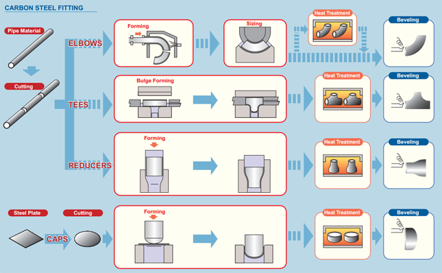
Requisiti del fasciame con piega a induzione a caldo
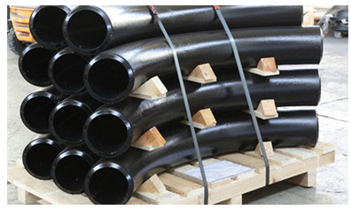
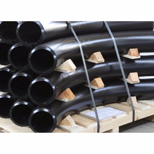
Ci concentriamo su ogni procedura per garantire la qualità, il pacchetto che di solito prendiamo è tavolare i gomiti dei tubi d'acciaio con sacchetti di polietilene ambientali, e poi in casse di legno con fumigazione gratuita o piastre di legno. Accettiamo anche pacchetti personalizzati come OEM tramite negoziazione.
- Il materiale dovrà essere imballato pronto per l'esportazione in modo da consentire una facile movimentazione e prevenire danni, il fornitore dovrà presentare all'acquirente la procedura di imballaggio standard per l'approvazione.
- Le estremità aperte del raccordo e le flange devono essere fornite con tappi o cappucci protettivi in plastica resistente. Per le estremità smussate, i cappucci devono proteggere l'intera area della smussatura.
- Per i materiali in acciaio inossidabile deve essere utilizzato un materiale barriera impermeabile per proteggerli dall'attacco del cloro causato dall'esposizione all'atmosfera di acqua salata.
- Gli articoli in acciaio al carbonio e in acciaio inossidabile non possono essere immagazzinati insieme e devono essere imballati separatamente.