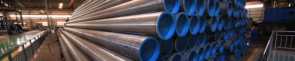
1. ثني الأنابيب:
ثني الأنبوب هو المصطلح الشامل لعمليات تشكيل المعادن المستخدمة لتشكيل الأنابيب أو الأنابيب بشكل دائم. يجب على المرء أن يفرق بين إجراءات ثني الشكل المرتبطة بالشكل والحرة، وكذلك بين إجراءات التشكيل المدعومة بالحرارة والباردة.
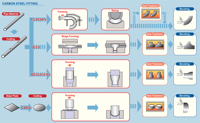
2. العمليات:
تبدأ عملية ثني الأنبوب بتحميل أنبوب في أنبوب أو ثني أنبوب وتثبيته في مكانه بين قالبين، وكتلة التثبيت وقالب التشكيل. يتم أيضًا تثبيت الأنبوب بشكل غير محكم بواسطة قالبين آخرين، قالب الماسحة وقالب الضغط.
تتضمن عملية ثني الأنبوب استخدام القوة الميكانيكية لدفع أنبوب المادة أو الأنابيب ضد القالب، مما يجبر الأنبوب أو الأنبوب على التوافق مع شكل القالب. في كثير من الأحيان، يتم تثبيت أنابيب المخزون بقوة في مكانها بينما يتم تدوير النهاية ولفها حول القالب. تشمل أشكال المعالجة الأخرى دفع المخزون عبر بكرات تثنيه إلى منحنى بسيط.[2] بالنسبة لبعض عمليات ثني الأنبوب، يتم وضع شياق داخل الأنبوب لمنع الانهيار. يتم تثبيت الأنبوب في حالة شد بواسطة قالب ممسحة لمنع أي تجعيد أثناء الضغط. عادة ما يتم تصنيع قالب المساحات من سبيكة أكثر ليونة مثل الألومنيوم أو النحاس لتجنب خدش أو إتلاف المادة التي يتم ثنيها.
الصحافة الانحناء:
من المحتمل أن تكون عملية الثني بالضغط هي أول عملية ثني تستخدم في الأنابيب والأنابيب الباردة. في هذه العملية يتم الضغط على قالب على شكل الانحناء على الأنبوب مما يجبر الأنبوب على ملاءمة شكل الانحناء. نظرًا لأن الأنبوب غير مدعوم داخليًا، هناك بعض التشوه في شكل الأنبوب، مما يؤدي إلى مقطع عرضي بيضاوي. يتم استخدام هذه العملية عندما لا يكون هناك حاجة إلى مقطع عرضي ثابت للأنبوب. على الرغم من أن قالبًا واحدًا يمكن أن ينتج أشكالًا مختلفة، إلا أنه يعمل فقط مع أنبوب ونصف قطر بحجم واحد.
الانحناء بالسحب الدوار:
الأدوات الكاملة لثني السحب الدوار
إن ثني السحب الدوار (RDB) هو تقنية دقيقة، لأنه ينحني باستخدام الأدوات أو "مجموعات القالب" التي لها نصف قطر خط مركزي ثابت (CLR)، ويُشار إليه بدلاً من ذلك على أنه نصف قطر الانحناء المتوسط (Rm).
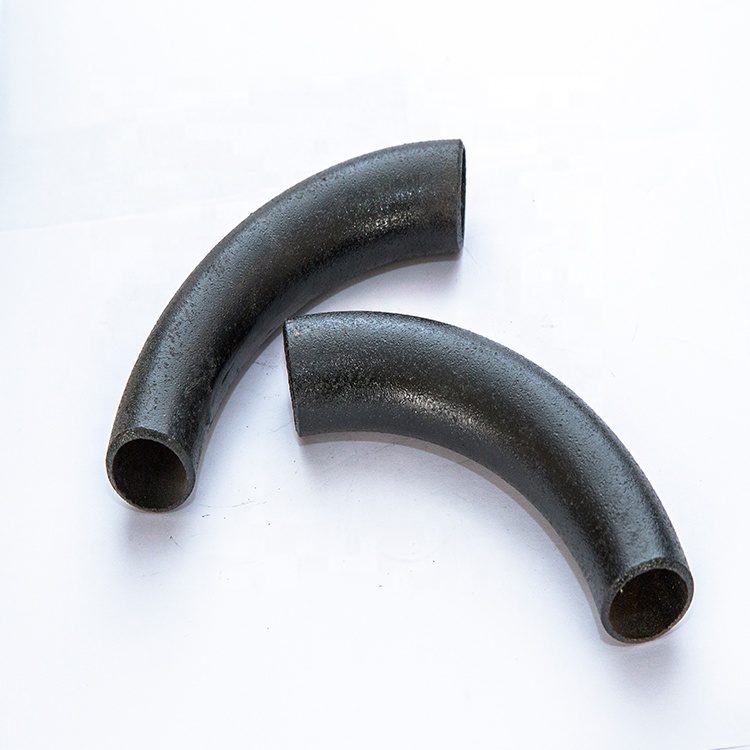
لفة الانحناء:
أثناء عملية ثني اللفة، يتم تمرير الأنبوب أو البثق أو المادة الصلبة من خلال سلسلة من البكرات (ثلاث عادةً) التي تطبق الضغط على الأنبوب مما يؤدي إلى تغيير نصف قطر الانحناء في الأنبوب تدريجيًا. تحتوي آلات ثني اللف ذات النمط الهرمي على لفة متحركة واحدة، وعادة ما تكون اللفة العلوية. تحتوي ماكينات ثني اللفة من النوع المزدوج على لفتين قابلتين للتعديل، عادة ما تكون اللفات السفلية، ولفة علوية ثابتة. تسبب طريقة الانحناء هذه تشوهًا بسيطًا جدًا في المقطع العرضي للأنبوب. هذه العملية مناسبة لإنتاج لفائف الأنابيب بالإضافة إلى الانحناءات الطويلة اللطيفة مثل تلك المستخدمة في أنظمة الجمالون.
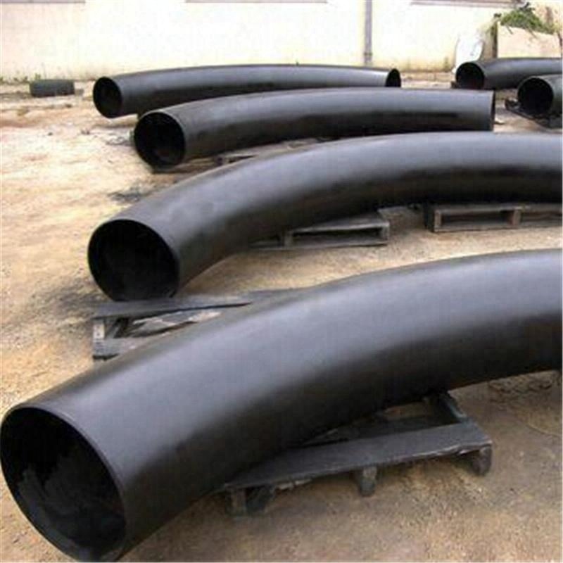
الانحناء التعريفي:
يتم وضع ملف تحريضي حول جزء صغير من الأنبوب عند نقطة الانحناء. ثم يتم تسخينه بالحث إلى ما بين 800 و2200 درجة فهرنهايت (430 و1200 درجة مئوية). عندما يكون الأنبوب ساخنًا، يتم الضغط على الأنبوب لثنيه. يمكن بعد ذلك إخماد الأنبوب إما برذاذ الهواء أو الماء أو تبريده ضد الهواء المحيط.
يتم استخدام الانحناء التعريفي لإنتاج الانحناءات لمجموعة واسعة من التطبيقات، مثل خطوط الأنابيب (ذات الجدران الرقيقة) لكل من المنبع والأسفل والقطاعات الداخلية والخارجية من صناعة البتروكيماويات، والأجزاء الهيكلية ذات نصف القطر الكبير لصناعة البناء والتشييد، منحنيات نصف قطرها سميكة الجدران وقصيرة لصناعة توليد الطاقة وأنظمة التدفئة في المدينة.
المزايا الكبيرة للثني التعريفي هي:
لا حاجة للشياق
يمكن اختيار نصف قطر الانحناء والزوايا (1°-180°) بحرية
أنصاف أقطار وزوايا الانحناء دقيقة للغاية
ويمكن بسهولة إنتاج مكبات الأنابيب الدقيقة
يمكن الحصول على وفورات كبيرة في اللحامات الميدانية
يمكن استيعاب مجموعة واسعة من أحجام الأنابيب في جهاز واحد (من 1 بوصة إلى 80 بوصة من القطر الخارجي)
ترقق الجدار وقيم البيضاوية ممتازة
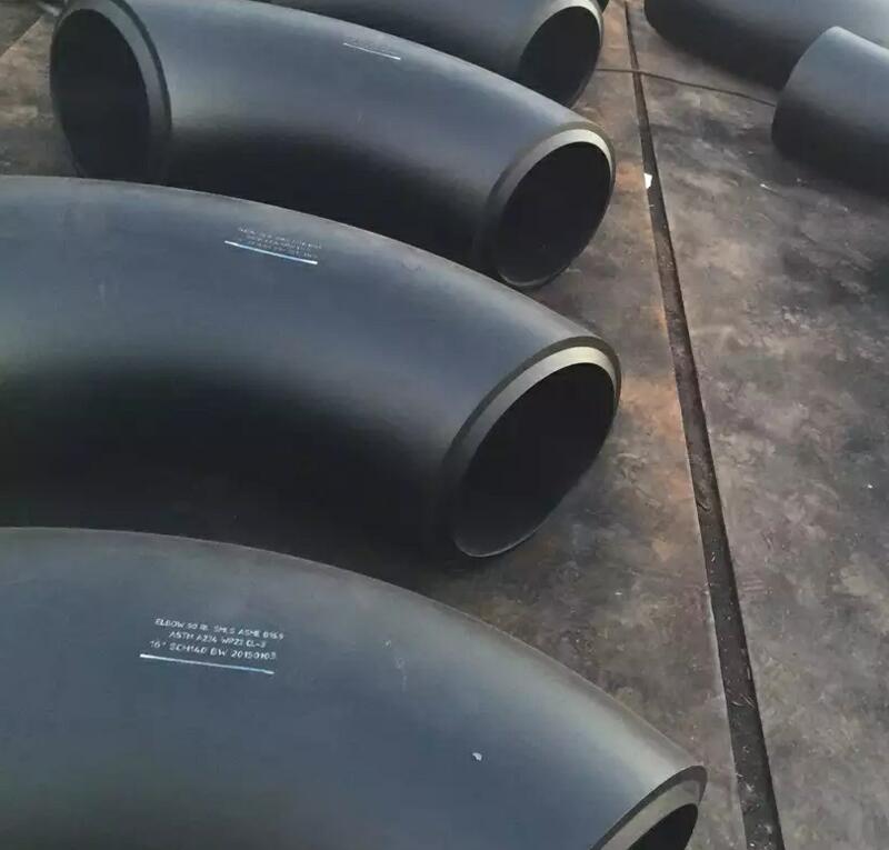
بالنسبة لأبعاد المنتج المطاوع (WP) تمت تغطيتها
ASME B16.9 - وهو المعيار القياسي لتركيبات اللحام التناكبي المصنوعة في المصنع لحجم NPS 1⁄₂ إلى NPS 48 بوصة و
وB16.28 - وهو المعيار الخاص بالمرفقين والإرجاع نصف القطر القصير الملحوم بالفولاذ المطاوع لحجم NPS 1⁄₂ إلى NPS 24 بوصة
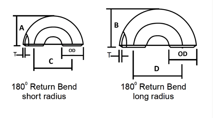
| حجم الأنبوب الاسمي | القطر الخارجي | العودة إلى الوجه | من المركز إلى المركز | ||
| بوصة. | OD | A | B | C | D |
| 1/2 | 21.3 | 48 | - | 76 | - |
| 3/4 | 26.7 | 43 | - | 57 | - |
| 1 | 33.4 | 56 | 41 | 76 | 51 |
| 1 1/4 | 42.2 | 70 | 52 | 95 | 64 |
| 1 1/2 | 48.3 | 83 | 62 | 114 | 76 |
| 2 | 60.3 | 106 | 81 | 152 | 102 |
| 2 1/2 | 73 | 132 | 100 | 191 | 127 |
| 3 | 88.9 | 159 | 121 | 229 | 152 |
| 3 1/2 | 101.6 | 184 | 140 | 267 | 178 |
| 4 | 114.3 | 210 | 159 | 305 | 203 |
| 5 | 141.3 | 262 | 197 | 381 | 254 |
| 6 | 168.3 | 313 | 237 | 457 | 305 |
| 8 | 219.1 | 414 | 313 | 610 | 406 |
| 10 | 273.1 | 518 | 391 | 762 | 508 |
| 12 | 323.9 | 619 | 467 | 914 | 610 |
| 14 | 355.6 | 711 | 533 | 1067 | 711 |
| 16 | 406.4 | 813 | 610 | 1219 | 813 |
| 18 | 457.2 | 914 | 686 | 1372 | 914 |
| 20 | 508 | 1016 | 762 | 1524 | 1016 |
| 22 | 559 | 1118 | 838 | 1676 | 1118 |
| 24 | 610 | 1219 | 914 | 1829 | 1219 |
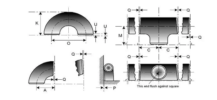
التسامح مع أبعاد تجهيزات الأنابيب حسب ASME B16.9
| حجم الأنبوب الاسمي | جميع التجهيزات | جميع التجهيزات | جميع التجهيزات | المرفقين والمحملات | 180 درجة انحناءات العودة | 180 درجة انحناءات العودة | 180 درجة انحناءات العودة | المخفضات | أحرف استهلالية |
| مصادر القدرة النووية | OD عند الشطب (1)، (2) | معرف في النهاية (1)، (3)، (4) | سمك الجدار (3) | البعد من المركز إلى النهاية A، B، C، M | مركز إلى مركز O | العودة لوجه ك | محاذاة النهايات U | الطول الكلي ح | الطول الكلي E |
| ½ إلى 2½ | 0.06 -0.03 | 0.03 | لا تقل عن 87.5% من السمك الاسمي | 0.06 | 0.25 | 0.25 | 0.03 | 0.06 | 0.12 |
| 3 إلى 3 ½ | 0.06 | 0.06 | لا تقل عن 87.5% من السمك الاسمي | 0.06 | 0.25 | 0.25 | 0.03 | 0.06 | 0.12 |
| 4 | 0.06 | 0.06 | لا تقل عن 87.5% من السمك الاسمي | 0.06 | 0.25 | 0.25 | 0.03 | 0.06 | 0.12 |
| 5 إلى 8 | 0.09 -0.06 | 0.06 | لا تقل عن 87.5% من السمك الاسمي | 0.06 | 0.25 | 0.25 | 0.03 | 0.06 | 0.25 |
| 10 إلى 18 | 0.16 -0.12 | 0.12 | لا تقل عن 87.5% من السمك الاسمي | 0.09 | 0.38 | 0.25 | 0.06 | 0.09 | 0.25 |
| 20 إلى 24 | 0.25 -0.19 | 0.19 | لا تقل عن 87.5% من السمك الاسمي | 0.09 | 0.38 | 0.25 | 0.06 | 0.09 | 0.25 |
| 26 إلى 30 | 0.25 -0.19 | 0.19 | لا تقل عن 87.5% من السمك الاسمي | 0.12 | … | … | … | 0.19 | 0.38 |
| 32 إلى 48 | 0.25 -0.19 | 0.19 | لا تقل عن 87.5% من السمك الاسمي | 0.19 | … | … | … | 0.19 | 0.38 |
سبائك النيكل
ASTM / ASME SB 336 UNS 2200 (NICKEL 200)، UNS 2201 (NICKEL 201)، UNS 4400 (MONEL 400)، UNS 8020 (ALLOY 20/20 CB 3، UNS 8825 INCONEL (825)، UNS 6600 (INCONEL 600)، UNS 6601 (INCONEL 601)، UNS 6625 (INCONEL 625)، UNS 10276 (HASTELLOY C 276)
الفولاذ المقاوم للصدأ
ASTM / ASME SA 403 GR WP “S” / “W” / “WX” 304، 304L، 304H، 304N، 304LN، 309، 310H، 316، 316H، 317، 317L، 321، 321H، 347، 347 H.
دوبلكس ستيل
ASTM / ASME SA 815 UNS NO.S 31803، S 32205، S 32550، S 32750، S 32760.
الكربون الصلب
ASTM / ASME A 234 WPB، WPC ASTM / ASME A 860 WPHY 42، WPHY 46، WPHY 52، WPH 60، WPHY 65 وWPHY 70.
سبائك الصلب
ASTM / ASME A 234 WP 1، WP 5، WP 9، WP 11، WP 12، WP 22، WP 23، WP 91.
| محتوى التركيب الكيميائي | الخواص الميكانيكية | ||||||||||
| رقم المادة | C | Mn | Si | S | P | Cr | Mo | Ni | قوة الشد | قوة العائد | استطالة |
| A234 وبب | .30.3 | 0.29-1.06 | ≥0.1 | .058.058 | .050.05 | / | / | / | 415-585 | ≥240 | ≥30 |
| A234 WP5 | .150.15 | .60.6 | .50.5 | .0.04 | .030.03 | 4-6 | 0.44-0.65 | / | 415-585 | ≥205 | ≥20 |
| A403 WP304 | .080.08 | ≥2 | ≥1 | .00.040 | .030.030 | 18-20 | / | 8-11 | ≥515 | ≥205 | ≥30 |
| A403 WP316L | .030.03 | ≥2 | ≥1 | .00.045 | .030.03 | 16-18 | 2-3 | 10-15 | ≥485 | ≥170 | ≥30 |
| WPHY60 | .20.20 | 1-1.45 | 0.15-0.4 | .00.015 | .030.030 | / | / | / | ≥515 | ≥415 | / |
تزييت خفيف، طلاء أسود، طلاء مضاد للتآكل PE /3PE
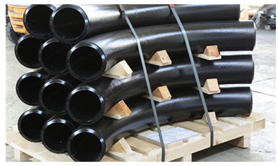
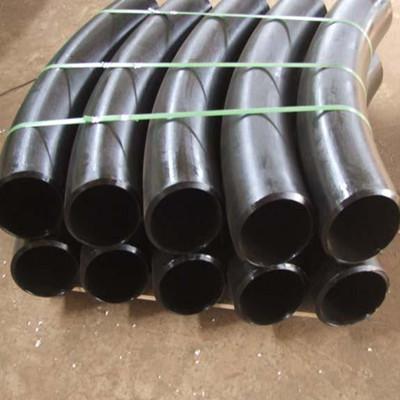
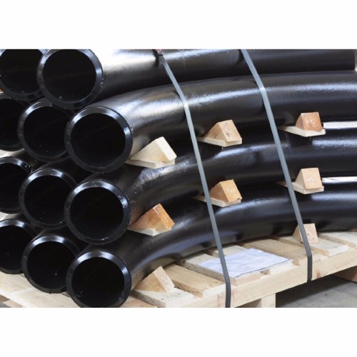
متطلبات الألواح الخشبية المنحنية بالحث الساخن
نحن نركز على كل إجراء لضمان الجودة، والحزمة التي نتخذها عادة هي لوح أكواع الأنابيب الفولاذية بأكياس بولي بيئية، ثم في حالات خشبية تبخير مجانية أو لوحة خشبية. كما نقبل الحزمة المخصصة مثل OEM عن طريق التفاوض.
- يجب تعبئة المواد جاهزة للتصدير بطريقة تتيح سهولة التعامل معها وتمنع الضرر، ويجب على البائع تقديم إجراءات التعبئة القياسية الخاصة به إلى المشتري للحصول على الموافقة.
- يجب أن يتم تزويد الأطراف المفتوحة للتركيبات والفلنجات بسدادات أو أغطية واقية بلاستيكية شديدة التحمل. بالنسبة للأطراف المشطوفة، يجب أن تحمي الأغطية كامل مساحة الشطبة.
- يجب استخدام مادة حاجزة مقاومة للماء لمواد الفولاذ المقاوم للصدأ للحماية من هجوم الكلور عن طريق التعرض لجو المياه المالحة.
- لا يُسمح بتخزين العناصر المصنوعة من الفولاذ الكربوني والفولاذ المقاوم للصدأ معًا ويجب تعبئتها بشكل منفصل.