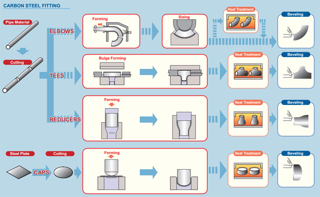
1. Zagiąć rurkę:
Gięcie rur to ogólny termin określający procesy formowania metalu stosowane do trwałego formowania rur. Należy rozróżnić procedury gięcia w formie związanej i swobodnej, a także procedury formowania na zimno i na gorąco.
2. Procesy:
Proces gięcia rur rozpoczyna się od załadowania rury do giętarki do rur lub rur i zaciśnięcia jej na miejscu pomiędzy dwiema matrycami, blokiem zaciskowym i matrycą formującą. Rurka jest również luźno trzymana przez dwie inne matryce, matrycę wycierającą i matrycę dociskową.
Proces gięcia rur polega na użyciu siły mechanicznej do dociskania rury lub rurki z materiału podstawowego do matrycy, zmuszając rurę lub rurkę do dostosowania się do kształtu matrycy. Często rurka podstawowa jest mocno utrzymywana na miejscu, podczas gdy koniec jest obracany i zwijany wokół matrycy. Inne formy przetwarzania, w tym przepychanie surowca przez rolki, które wyginają go w prostą krzywiznę.[2] W przypadku niektórych procesów gięcia rur, wewnątrz rury umieszcza się trzpień, aby zapobiec zapadaniu się. Rurka jest utrzymywana w napięciu za pomocą matrycy wycierającej, aby zapobiec zagnieceniom podczas naprężenia. Matryca wycierająca jest zwykle wykonana z bardziej miękkiego stopu, takiego jak aluminium lub mosiądz, aby uniknąć zarysowania lub uszkodzenia giętego materiału.
Gięcie w prasie:
Gięcie w prasie jest prawdopodobnie pierwszym procesem gięcia stosowanym w przypadku zimnych rur i rurek. W procesie tym do rury dociskana jest matryca w kształcie zagięcia, dociskając rurę do kształtu zagięcia. Ponieważ rura nie jest podparta wewnętrznie, następuje pewne odkształcenie kształtu rury, w wyniku czego powstaje owalny przekrój poprzeczny. Proces ten stosuje się tam, gdzie nie jest wymagany stały przekrój rury. Chociaż pojedyncza matryca może wytwarzać różne kształty, działa tylko w przypadku rury o jednym rozmiarze i promieniu.
Gięcie obrotowe:
Pełne oprzyrządowanie do gięcia obrotowego
Gięcie obrotowe (RDB) to precyzyjna technologia, ponieważ gięcie odbywa się przy użyciu oprzyrządowania lub „zestawów matryc”, które mają stały promień linii środkowej (CLR), alternatywnie oznaczany jako średni promień zgięcia (Rm).
Gięcie rolek:
Podczas procesu gięcia na rolkach rura, wytłoczka lub bryła przechodzi przez szereg rolek (zwykle trzy), które wywierają nacisk na rurę, stopniowo zmieniając promień zgięcia rury. Giętarki rolkowe w kształcie piramidy mają jedną ruchomą rolkę, zwykle górną. Giętarki rolkowe z podwójnym zaciskiem mają dwie regulowane rolki, zwykle rolki dolne i stałą rolkę górną. Ta metoda gięcia powoduje bardzo małe odkształcenia przekroju rury. Proces ten nadaje się do wytwarzania zwojów rur, a także długich, delikatnych zagięć, takich jak te stosowane w systemach kratownicowych.
Gięcie indukcyjne:
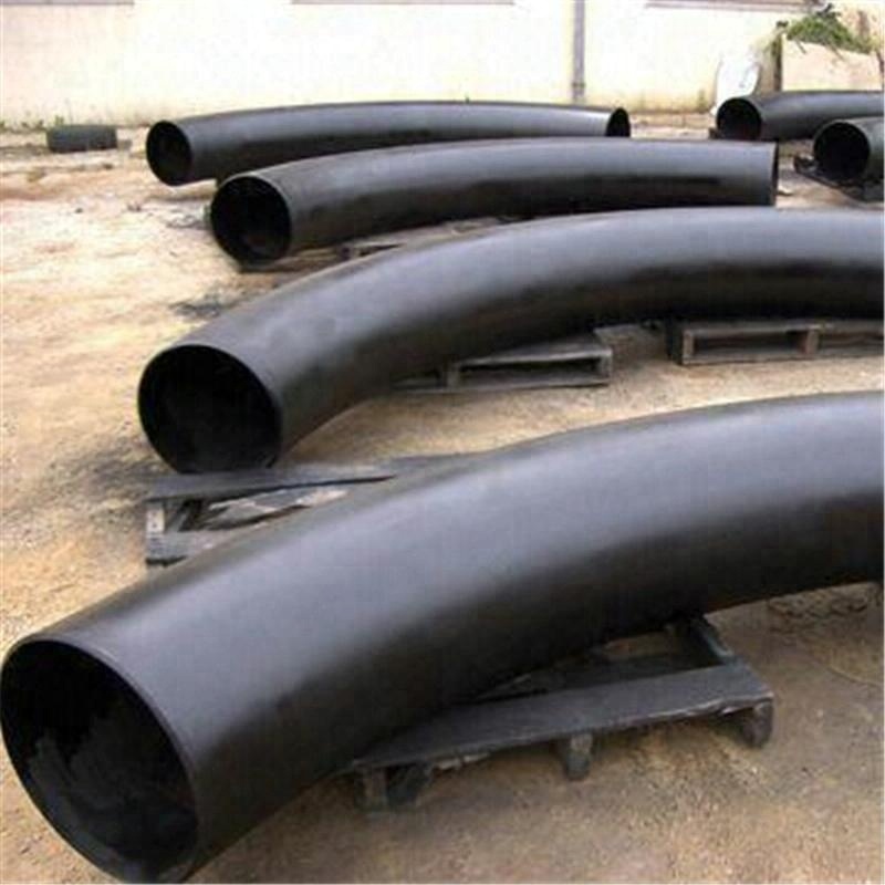
Cewka indukcyjna jest umieszczona wokół małego odcinka rury w miejscu zagięcia. Następnie jest podgrzewany indukcyjnie do temperatury od 800 do 2200 stopni Fahrenheita (430 do 1200 C). Gdy rura jest gorąca, na rurę wywierany jest nacisk w celu jej zgięcia. Następnie rurę można hartować za pomocą natrysku powietrza lub wody albo schłodzić powietrzem otoczenia.
Gięcie indukcyjne wykorzystywane jest do wytwarzania łuków do szerokiego zakresu zastosowań, takich jak (cienkościenne) rurociągi dla segmentów rurociągów w górę i w dół oraz na lądzie i na morzu w przemyśle petrochemicznym, części konstrukcyjne o dużych promieniach dla przemysłu budowlanego, grubościenne łuki o małym promieniu dla energetyki i ciepłownictwa miejskiego.
Dużymi zaletami gięcia indukcyjnego są:
nie ma potrzeby stosowania trzpieni
promienie i kąty gięcia (1°-180°) można dowolnie wybierać
bardzo dokładne promienie i kąty zgięcia
można łatwo wyprodukować dokładne szpule rurowe
znaczne oszczędności można uzyskać w przypadku spoin polowych
w jednej maszynie można obsłużyć szeroki zakres rozmiarów rur (od 1” do 80” OD)
doskonałe wartości pocienienia ścianek i owalności
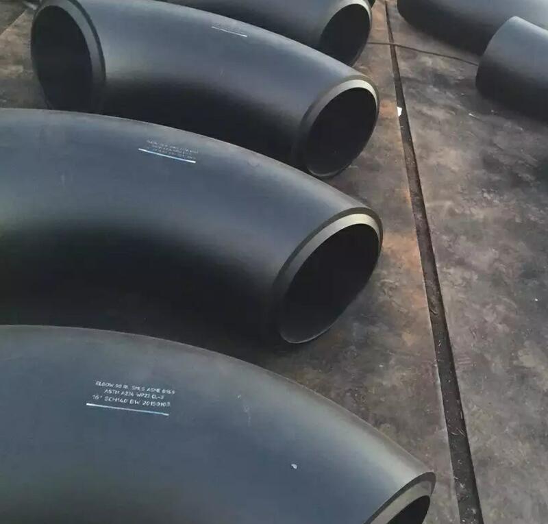
W przypadku wyrobów kutych (WP) wymiar jest objęty
ASME B16.9 – który jest standardem dla produkowanych fabrycznie złączek do zgrzewania doczołowego z kutego materiału dla rozmiarów NPS 1⁄₂ do NPS 48” i
Oraz B16.28 – który jest standardem dla kolanek i powrotów ze stali kutej do spawania doczołowego o krótkim promieniu i powrotów dla rozmiarów NPS 1⁄₂ do NPS 24”
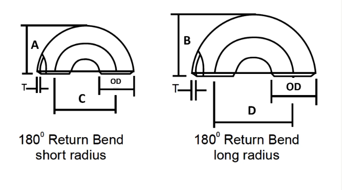
| NOMINALNY ROZMIAR RURY | ŚREDNICA ZEWNĘTRZNA | Z POWROTEM W TWARZ | CENTRUM DO CENTRUM | ||
| Cal. | OD | A | B | C | D |
| 1/2 | 21.3 | 48 | – | 76 | – |
| 3/4 | 26,7 | 43 | – | 57 | – |
| 1 | 33,4 | 56 | 41 | 76 | 51 |
| 1 1/4 | 42.2 | 70 | 52 | 95 | 64 |
| 1 1/2 | 48.3 | 83 | 62 | 114 | 76 |
| 2 | 60.3 | 106 | 81 | 152 | 102 |
| 2 1/2 | 73 | 132 | 100 | 191 | 127 |
| 3 | 88,9 | 159 | 121 | 229 | 152 |
| 3 1/2 | 101,6 | 184 | 140 | 267 | 178 |
| 4 | 114,3 | 210 | 159 | 305 | 203 |
| 5 | 141,3 | 262 | 197 | 381 | 254 |
| 6 | 168,3 | 313 | 237 | 457 | 305 |
| 8 | 219.1 | 414 | 313 | 610 | 406 |
| 10 | 273.1 | 518 | 391 | 762 | 508 |
| 12 | 323,9 | 619 | 467 | 914 | 610 |
| 14 | 355,6 | 711 | 533 | 1067 | 711 |
| 16 | 406,4 | 813 | 610 | 1219 | 813 |
| 18 | 457.2 | 914 | 686 | 1372 | 914 |
| 20 | 508 | 1016 | 762 | 1524 | 1016 |
| 22 | 559 | 1118 | 838 | 1676 | 1118 |
| 24 | 610 | 1219 | 914 | 1829 | 1219 |
Tolerancja wymiarów łączników rurowych zgodnie z ASME B16.9
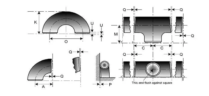
| NOMINALNY ROZMIAR RURY | WSZYSTKIE WYPOSAŻENIE | WSZYSTKIE WYPOSAŻENIE | WSZYSTKIE WYPOSAŻENIE | ŁOKCIA I TRÓJNIKI | ZGIĘCIE POWROTNE 180 STOPNI | ZGIĘCIE POWROTNE 180 STOPNI | ZGIĘCIE POWROTNE 180 STOPNI | REDUKCJE | CZAPKI |
| NPS | OD przy skosie (1), (2) | Identyfikator na końcu (1), (3), (4) | Grubość ścianki (3) | Wymiar od środka do końca A, B, C, M | Centrum do Centrum O | Spotkanie twarzą w twarz K | Wyrównanie końcówek U | Długość całkowita H | Długość całkowita E |
| ½ do 2½ | 0,06 -0,03 | 0,03 | Nie mniej niż 87,5% grubości nominalnej | 0,06 | 0,25 | 0,25 | 0,03 | 0,06 | 0,12 |
| 3 do 3 ½ | 0,06 | 0,06 | Nie mniej niż 87,5% grubości nominalnej | 0,06 | 0,25 | 0,25 | 0,03 | 0,06 | 0,12 |
| 4 | 0,06 | 0,06 | Nie mniej niż 87,5% grubości nominalnej | 0,06 | 0,25 | 0,25 | 0,03 | 0,06 | 0,12 |
| 5 do 8 | 0,09 -0,06 | 0,06 | Nie mniej niż 87,5% grubości nominalnej | 0,06 | 0,25 | 0,25 | 0,03 | 0,06 | 0,25 |
| 10 do 18 | 0,16 -0,12 | 0,12 | Nie mniej niż 87,5% grubości nominalnej | 0,09 | 0,38 | 0,25 | 0,06 | 0,09 | 0,25 |
| 20 do 24 | 0,25 -0,19 | 0,19 | Nie mniej niż 87,5% grubości nominalnej | 0,09 | 0,38 | 0,25 | 0,06 | 0,09 | 0,25 |
| 26 do 30 | 0,25 -0,19 | 0,19 | Nie mniej niż 87,5% grubości nominalnej | 0,12 | … | … | … | 0,19 | 0,38 |
| 32 do 48 | 0,25 -0,19 | 0,19 | Nie mniej niż 87,5% grubości nominalnej | 0,19 | … | … | … | 0,19 | 0,38 |
Stop niklu
ASTM / ASME SB 336 UNS 2200 ( NIKIEL 200 ), UNS 2201 (NIKIEL 201 ), UNS 4400 (MONEL 400 ), UNS 8020 ( ALLOY 20 / 20 CB 3, UNS 8825 INCONEL (825), UNS 6600 (INCONEL 600 ), UNS 6601 ( INCONEL 601 ), UNS 6625 (INCONEL 625), UNS 10276 ( HASTELLOY C 276 )
Stal nierdzewna
ASTM / ASME SA 403 GR WP „S” / „W” / „WX” 304 , 304L, 304H, 304N, 304LN, 309, 310H, 316, 316H, 317, 317L, 321, 321H, 347, 347 H.
Stal dupleksowa
ASTM/ASME SA 815 UNS nr 31803, S 32205, S 32550, S 32750, S 32760.
Stal węglowa
ASTM / ASME A 234 WPB, WPC ASTM / ASME A 860 WPHY 42, WPHY 46, WPHY 52, WPH 60, WPHY 65 i WPHY 70.
Stal stopowa
ASTM/ASME A 234 WP 1, WP 5, WP 9, WP 11, WP 12, WP 22, WP 23, WP 91.
| Zawartość składu chemicznego | Właściwości mechaniczne | ||||||||||
| Nr materiału | C | Mn | Si | S | P | Cr | Mo | Ni | Wytrzymałość na rozciąganie | Siła plastyczności | Wydłużenie |
| A234 WPB | ≤0,3 | 0,29-1,06 | ≥0,1 | ≤0,058 | ≤0,05 | / | / | / | 415-585 | ≥240 | ≥30 |
| A234 WP5 | ≤0,15 | ≤0,6 | ≤0,5 | ≤0,04 | ≤0,03 | 4-6 | 0,44-0,65 | / | 415-585 | ≥205 | ≥20 |
| A403 WP304 | ≤0,08 | ≤2 | ≤1 | ≤0,040 | ≤0,030 | 18-20 | / | 8-11 | ≥515 | ≥205 | ≥30 |
| A403 WP316L | ≤0,03 | ≤2 | ≤1 | ≤0,045 | ≤0,03 | 16-18 | 2-3 | 10-15 | ≥485 | ≥170 | ≥30 |
| WPHY60 | ≤0,20 | 1-1,45 | 0,15-0,4 | ≤0,015 | ≤0,030 | / | / | / | ≥515 | ≥415 | / |
Lekkie olejowanie, malowanie na czarno, powłoka antykorozyjna PE/3PE
Wymagania dotyczące poszycia zginanego na gorąco metodą indukcyjną
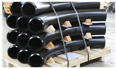
Koncentrujemy się na każdej procedurze, aby zapewnić jakość, pakiet, który zwykle przyjmujemy, to deskowanie kolanek rur stalowych za pomocą ekologicznych torebek foliowych, a następnie w drewnianych skrzyniach lub drewnianej płycie do bezpłatnej fumigacji. Akceptujemy również niestandardowe pakiety, takie jak OEM, w drodze negocjacji.
- Materiał powinien być zapakowany gotowy do eksportu w sposób umożliwiający łatwą obsługę i zapobiegający uszkodzeniom, sprzedawca przedłoży kupującemu do zatwierdzenia swoją standardową procedurę pakowania.
- Otwarte końce kształtek i kołnierze powinny być wyposażone w wytrzymałe plastikowe zatyczki lub zaślepki ochronne. W przypadku końców skośnych zaślepki powinny chronić całą powierzchnię skosu.
- W przypadku materiałów ze stali nierdzewnej należy zastosować wodoodporny materiał barierowy w celu ochrony przed atakiem chloru w wyniku wystawienia na działanie atmosfery słonej wody.
- Artykuły ze stali węglowej i stali nierdzewnej nie mogą być przechowywane razem i powinny być pakowane oddzielnie.