1. Согните трубку:
Гибка труб — это общий термин, обозначающий процессы обработки металлов давлением, используемые для постоянного формирования труб или трубок. Необходимо различать процедуры гибки со связанной и свободной формой, а также между процедурами термической и холодной формовки.
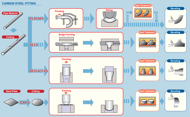
2. Процессы:
Гибка труб как процесс начинается с загрузки трубы в трубогиб или трубогиб и зажима ее между двумя матрицами, зажимным блоком и формовочной матрицей. Трубка также свободно удерживается двумя другими матрицами: скребковой матрицей и нажимной матрицей.
Процесс гибки труб включает в себя использование механической силы для прижатия трубы или трубки из исходного материала к матрице, заставляя трубу или трубку принимать форму матрицы. Часто стандартная трубка прочно удерживается на месте, пока ее конец вращается и обкатывается вокруг матрицы. Другие формы обработки, включая проталкивание заготовки через ролики, которые сгибают ее по простой кривой.[2] При некоторых операциях гибки труб внутри трубы помещается оправка, чтобы предотвратить ее разрушение. Трубка удерживается в натяжении с помощью скребка, чтобы предотвратить образование складок во время нагрузки. Пластина зачистки обычно изготавливается из более мягкого сплава, такого как алюминий или латунь, чтобы избежать царапин или повреждения сгибаемого материала.
Пресс-гибка:
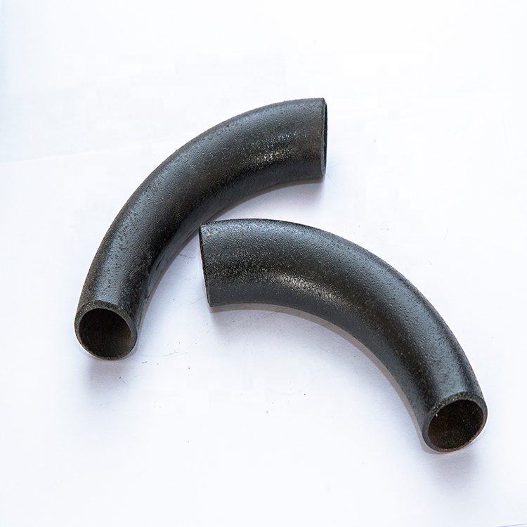
Гибка прессом, вероятно, является первым процессом гибки труб в холодном состоянии. В этом процессе к трубе прижимается матрица в форме изгиба, заставляя трубу соответствовать форме изгиба. Поскольку труба не имеет внутренней опоры, происходит некоторая деформация формы трубы, в результате чего поперечное сечение становится овальным. Этот процесс используется там, где не требуется постоянное поперечное сечение трубы. Хотя с помощью одной матрицы можно изготавливать различные формы, она подходит только для труб одного размера и радиуса.
Ротационная гибка:
Полный набор инструментов для ротационной гибки
Гибка вращающейся вытяжкой (RDB) представляет собой точную технологию, поскольку она сгибается с использованием инструментов или «наборов штампов», которые имеют постоянный радиус центральной линии (CLR), альтернативно обозначаемый как средний радиус изгиба (Rm).
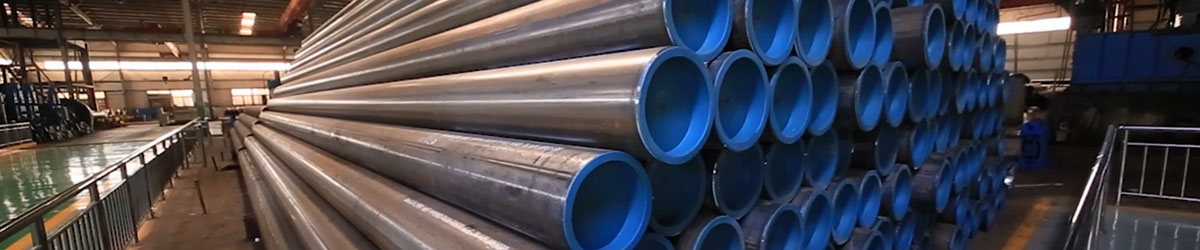
Гибка валков:
В процессе гибки валками труба, экструзия или твердое тело пропускается через ряд роликов (обычно три), которые оказывают давление на трубу, постепенно изменяя радиус изгиба трубы. Валковые гибочные машины пирамидального типа имеют один подвижный валок, обычно верхний. Валковые гибочные машины с двойным зажимом имеют два регулируемых валка, обычно нижний, и фиксированный верхний валок. Этот метод изгиба вызывает очень небольшую деформацию поперечного сечения трубы. Этот процесс подходит для изготовления бухт труб, а также длинных пологих изгибов, подобных тем, которые используются в ферменных системах.
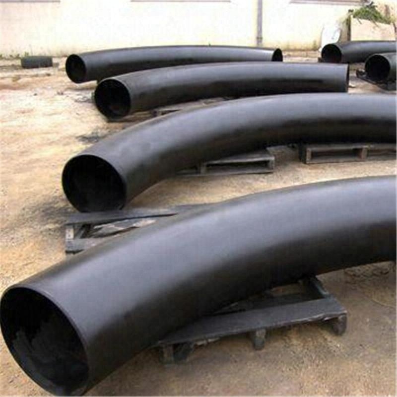
Индукционная гибка:
Индукционная катушка размещается вокруг небольшого участка трубы в месте изгиба. Затем его подвергают индукционному нагреву до температуры от 800 до 2200 градусов по Фаренгейту (от 430 до 1200 C). Пока труба горячая, на трубу оказывается давление, сгибающее ее. Затем трубу можно закалить распылением воздуха или воды или охладить окружающим воздухом.
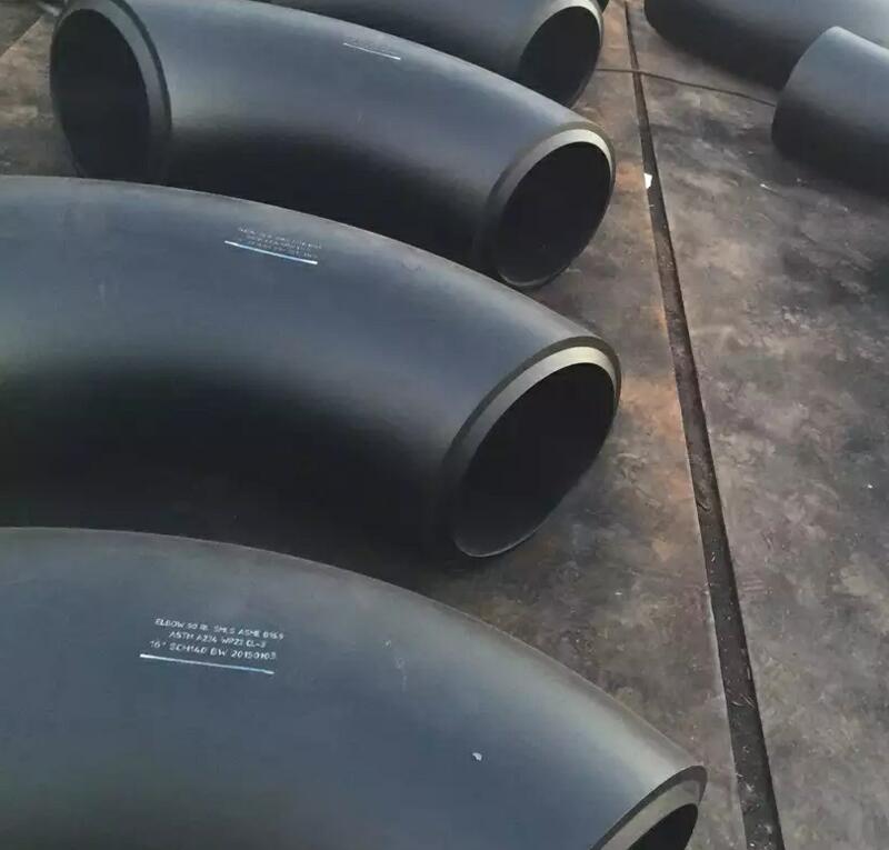
Индукционная гибка используется для изготовления отводов для широкого спектра применений, таких как (тонкостенные) трубопроводы для восходящего и нисходящего потока, а также для наземных и морских сегментов нефтехимической промышленности, конструкционные детали большого радиуса для строительной отрасли, Отводы с толстыми стенками и коротким радиусом для электроэнергетики и городских теплосетей.
Большими преимуществами индукционной гибки являются:
нет необходимости в оправках
радиусы и углы изгиба (1°-180°) могут выбираться свободно
очень точные радиусы и углы изгиба
можно легко изготовить точные катушки для труб
значительная экономия может быть получена при сварке в полевых условиях
В одной машине можно разместить трубы широкого диапазона размеров (наружный диаметр от 1 до 80 дюймов).
превосходные показатели утончения стенок и овальности
Для кованого изделия (WP) размер описан в
ASME B16.9 – стандарт для фабричных кованых фитингов для стыковой сварки для размеров от NPS 1⁄₂ до NPS 48 дюймов и
И B16.28, который является стандартным для колен и возвратных частей короткого радиуса из кованой стали, приваренных встык, для размеров от NPS 1/₂ до NPS 24 дюйма.
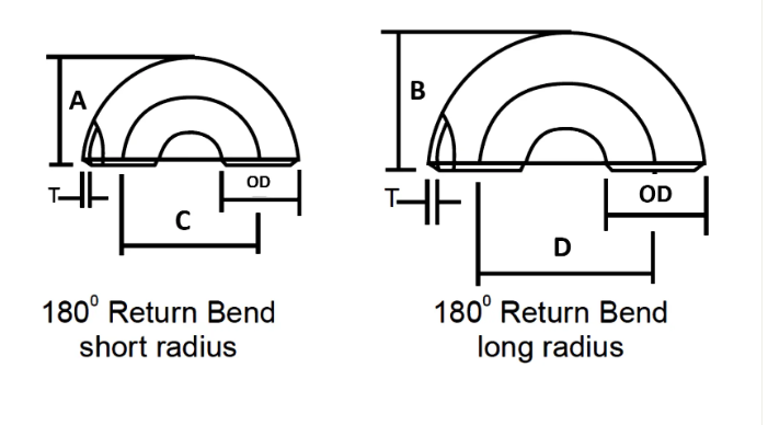
| НОМИНАЛЬНЫЙ РАЗМЕР ТРУБЫ | НАРУЖНЫЙ ДИАМЕТР | ВЕРНУТЬСЯ К ЛИЦУ | ОТ ЦЕНТРА К ЦЕНТРУ | ||
| Дюйм. | OD | A | B | C | D |
| 1/2 | 21,3 | 48 | – | 76 | – |
| 3/4 | 26,7 | 43 | – | 57 | – |
| 1 | 33,4 | 56 | 41 | 76 | 51 |
| 1 1/4 | 42,2 | 70 | 52 | 95 | 64 |
| 1 1/2 | 48,3 | 83 | 62 | 114 | 76 |
| 2 | 60,3 | 106 | 81 | 152 | 102 |
| 2 1/2 | 73 | 132 | 100 | 191 | 127 |
| 3 | 88,9 | 159 | 121 | 229 | 152 |
| 3 1/2 | 101,6 | 184 | 140 | 267 | 178 |
| 4 | 114,3 | 210 | 159 | 305 | 203 |
| 5 | 141,3 | 262 | 197 | 381 | 254 |
| 6 | 168,3 | 313 | 237 | 457 | 305 |
| 8 | 219,1 | 414 | 313 | 610 | 406 |
| 10 | 273,1 | 518 | 391 | 762 | 508 |
| 12 | 323,9 | 619 | 467 | 914 | 610 |
| 14 | 355,6 | 711 | 533 | 1067 | 711 |
| 16 | 406,4 | 813 | 610 | 1219 | 813 |
| 18 | 457,2 | 914 | 686 | 1372 | 914 |
| 20 | 508 | 1016 | 762 | 1524 г. | 1016 |
| 22 | 559 | 1118 | 838 | 1676 г. | 1118 |
| 24 | 610 | 1219 | 914 | 1829 г. | 1219 |
Допуски размеров трубной арматуры согласно ASME B16.9
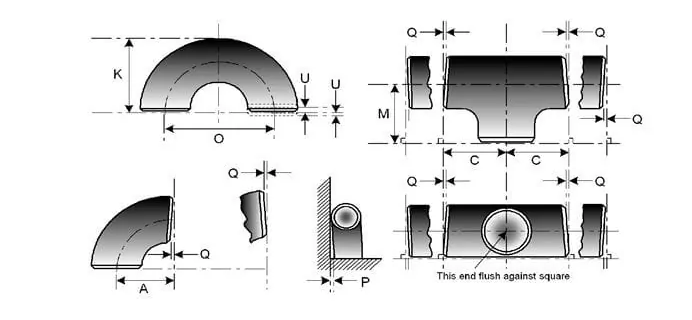
| НОМИНАЛЬНЫЙ РАЗМЕР ТРУБЫ | ВСЕ ФИТИНГИ | ВСЕ ФИТИНГИ | ВСЕ ФИТИНГИ | КОЛЕНА И ТРОЙНИКИ | ИЗГИБЫ ВОЗВРАТА НА 180 ГРАДУСОВ | ИЗГИБЫ ВОЗВРАТА НА 180 ГРАДУСОВ | ИЗГИБЫ ВОЗВРАТА НА 180 ГРАДУСОВ | РЕДУКТОРЫ | КАПС |
| НПС | OD на скосе (1), (2) | Идентификатор в конце (1), (3), (4) | Толщина стенки (3) | Межцентровое расстояние A,B,C,M | От центра к центру O | спиной к лицу К | Выравнивание концов U | Общая длина H | Общая длина E |
| от ½ до 2½ | 0,06 -0,03 | 0,03 | Не менее 87,5% номинальной толщины | 0,06 | 0,25 | 0,25 | 0,03 | 0,06 | 0,12 |
| от 3 до 3 ½ | 0,06 | 0,06 | Не менее 87,5% номинальной толщины | 0,06 | 0,25 | 0,25 | 0,03 | 0,06 | 0,12 |
| 4 | 0,06 | 0,06 | Не менее 87,5% номинальной толщины | 0,06 | 0,25 | 0,25 | 0,03 | 0,06 | 0,12 |
| от 5 до 8 | 0,09 -0,06 | 0,06 | Не менее 87,5% номинальной толщины | 0,06 | 0,25 | 0,25 | 0,03 | 0,06 | 0,25 |
| с 10 до 18 | 0,16 -0,12 | 0,12 | Не менее 87,5% номинальной толщины | 0,09 | 0,38 | 0,25 | 0,06 | 0,09 | 0,25 |
| с 20 до 24 | 0,25 -0,19 | 0,19 | Не менее 87,5% номинальной толщины | 0,09 | 0,38 | 0,25 | 0,06 | 0,09 | 0,25 |
| с 26 до 30 | 0,25 -0,19 | 0,19 | Не менее 87,5% номинальной толщины | 0,12 | … | … | … | 0,19 | 0,38 |
| от 32 до 48 | 0,25 -0,19 | 0,19 | Не менее 87,5% номинальной толщины | 0,19 | … | … | … | 0,19 | 0,38 |
Никелевый сплав
ASTM/ASME SB 336 UNS 2200 (НИКЕЛЬ 200), UNS 2201 (НИКЕЛЬ 201), UNS 4400 (МОНЕЛЬ 400), UNS 8020 (СПЛАВ 20/20 CB 3, UNS 8825 ИНКОНЕЛЬ (825), UNS 6600 (ИНКОНЕЛЬ 600), UNS 6601 (ИНКОНЕЛЬ 601), UNS 6625 (ИНКОНЕЛЬ 625), UNS 10276 (ХАСТЕЛОЙ C 276)
Нержавеющая сталь
ASTM / ASME SA 403 GR WP «S» / «W» / «WX» 304, 304L, 304H, 304N, 304LN, 309, 310H, 316, 316H, 317, 317L, 321, 321H, 347, 347 H.
Дуплексная сталь
ASTM/ASME SA 815 UNS № S 31803, S 32205, S 32550, S 32750, S 32760.
Углеродистая сталь
ASTM/ASME A 234 WPB, WPC ASTM/ASME A 860 WPHY 42, WPHY 46, WPHY 52, WPH 60, WPHY 65 и WPHY 70.
Легированная сталь
ASTM/ASME A 234 WP 1, WP 5, WP 9, WP 11, WP 12, WP 22, WP 23, WP 91.
| Химический состав Содержание | Механические свойства | ||||||||||
| Материал НЕТ | C | Mn | Si | S | P | Cr | Mo | Ni | Предел прочности | Предел текучести | удлинение |
| А234 WPB | ≤0,3 | 0,29-1,06 | ≥0,1 | ≤0,058 | ≤0,05 | / | / | / | 415-585 | ≥240 | ≥30 |
| А234 WP5 | ≤0,15 | ≤0,6 | ≤0,5 | ≤0,04 | ≤0,03 | 4-6 | 0,44-0,65 | / | 415-585 | ≥205 | ≥20 |
| А403 WP304 | ≤0,08 | ≤2 | ≤1 | ≤0,040 | ≤0,030 | 18-20 | / | 8-11 | ≥515 | ≥205 | ≥30 |
| А403 WP316L | ≤0,03 | ≤2 | ≤1 | ≤0,045 | ≤0,03 | 16-18 | 2-3 | 10-15 | ≥485 | ≥170 | ≥30 |
| WPHY60 | ≤0,20 | 1-1,45 | 0,15-0,4 | ≤0,015 | ≤0,030 | / | / | / | ≥515 | ≥415 | / |
Легкая смазка, черная окраска, антикоррозионное покрытие PE/3PE
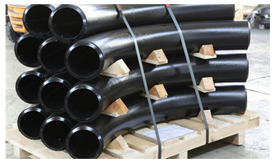
Требования к обшивке с изгибом под воздействием горячей индукции
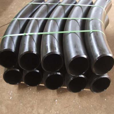
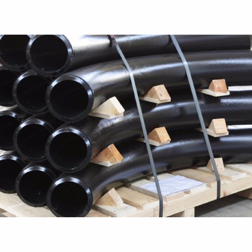
Мы уделяем особое внимание каждой процедуре, чтобы обеспечить качество, упаковка, которую мы обычно берем, представляет собой обшивку колен стальных труб экологически чистыми полиэтиленовыми пакетами, а затем в деревянных ящиках или деревянных пластинах с бесплатной фумигацией. Мы также принимаем индивидуальные упаковки, такие как OEM, путем переговоров.
- Материал должен быть упакован для экспорта таким образом, чтобы обеспечить удобство обращения и предотвратить повреждение. Поставщик должен представить покупателю на утверждение стандартную процедуру упаковки.
- Открытые концы фитингов и фланцев должны быть снабжены прочными пластиковыми защитными заглушками или колпачками. Для скошенных концов колпачки должны защищать всю площадь скоса.
- Для материалов из нержавеющей стали должен использоваться водонепроницаемый барьерный материал для защиты от воздействия хлора при воздействии атмосферы соленой воды.
- Предметы из углеродистой и нержавеющей стали не разрешается хранить вместе и должны упаковываться отдельно.